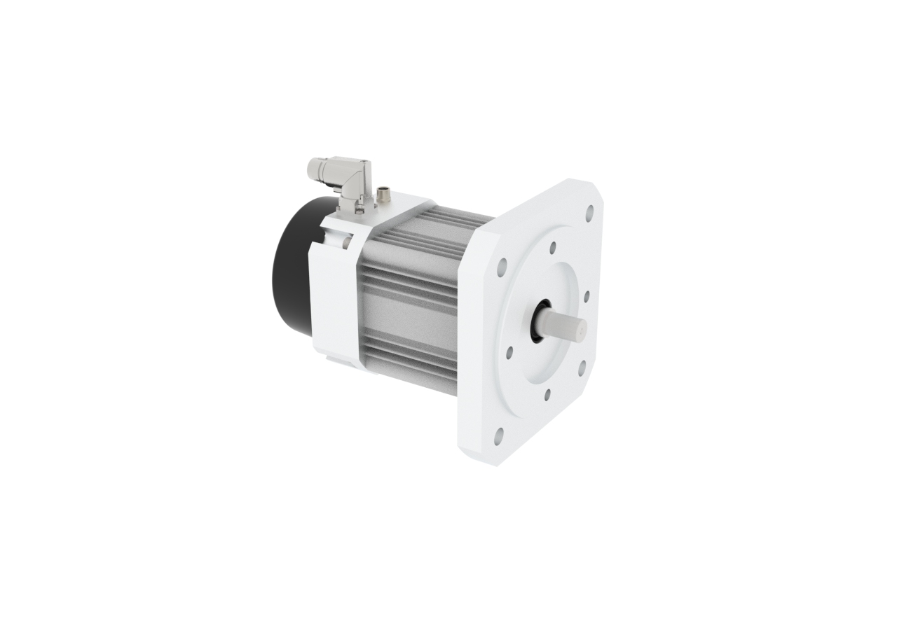
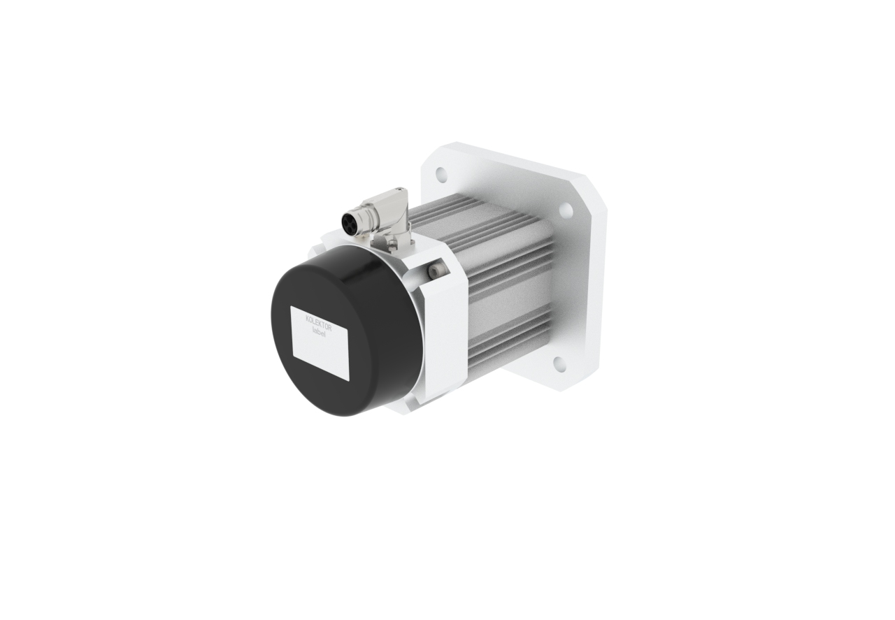
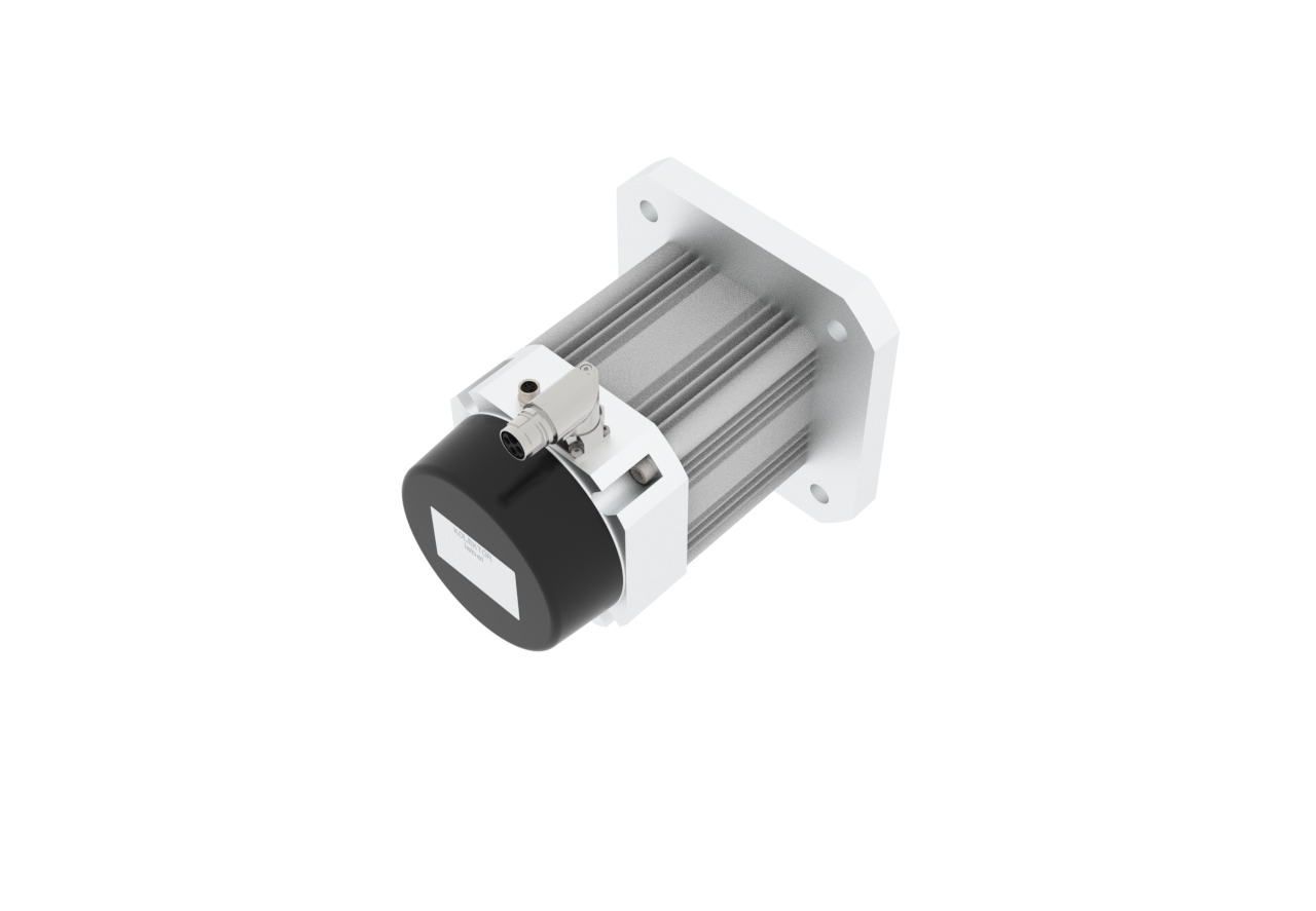
PMBL Drive | BL90/70
Compact drive for electrified applications |
||
|
Integrared Motor Controler |
Compact design Surface mounted permanent magnets |
Ready for pump integration |
TECHNICAL DATA
|
Nominal DC voltage [V] |
24 |
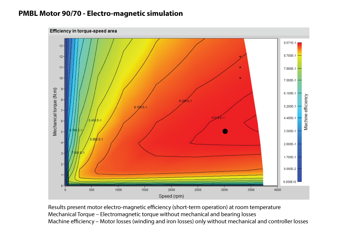
Nominal torque [Nm] |
5
|
No load speed [RPM] |
TBD |
| Motor working temperature range [°C] Motor winding max temperature [°C] Motor ambient temperature range [°C] Motor cooling (medium, temp) |
TBD 130 TBD air |
Weight [kg] Rotor inertia [E-5 kg-mm2] Protection clas Gearbox ratio Wheel load [kg] Connection geometry |
TBD TBD IP67 n/a n/a IEC 60072-1 FF165 |
Brake nominal voltage [V] Brake resistance [Ohm] Brake holding torque [Nm] Temperature sensor type Encoder sensor operation voltage Encoder sensor type |
n/a n/a n/a PT 1000 n/a n/a n/a |
|
Communication Communication protocol |
CAN |
Electrical connection type Communication connector type |
TE Power connector 917 M8 CAN connector |
||
|
Other notes |
Performance charts represent simulation results - short therm operation |
||||


